|
|
The information presented on this page is the product of my own experience and research only. I received no help or approval from either Carter or Ford. I have no formal automotive qualifications and no formal expertise with cars or carburettors. Reference sources are credited below.
The Carter Thermoquad carburettor was fitted to Australian manufactured Ford vehicles fitted with V8 petrol engines and built between 1977 and 1982. These years correspond to the Falcon models XC through to XE. It is an American designed and built carburettor, and was original equipment on many American Chrysler V8 vehicles built during the 1970s.
As fitted to Australian vehicles, the Thermoquad is a two-stage four-barrell carburettor with electrically activated automatic choke. It is a spreadbore design, with secondary throats twice the size of the primaries. The secondary throttles are opened by a mechanical linkage to the primary throttles, starting to open when the primary throttles are roughly 3/4 open, with both primary and secondary throttles becoming fully open at the same time. A spring loaded, vacuum operated air-door above the secondary throats prevents airflow through the secondaries until engine demands are sufficient to use the extra flow, thus aiding a smooth transition to wide-open throttle.
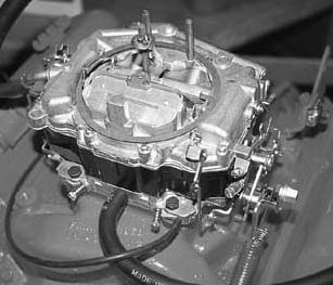
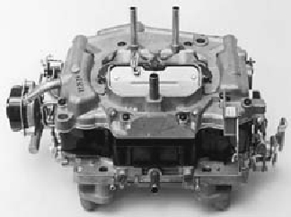
The Carter Thermoquad features a plastic (phrenolic resin, actually) main body (visible as the dark centre section in the above photographs). The main body contains the fuel reservoir, and the plastic construction is claimed to keep the fuel cooler than a metal body would, thus enabling more accurate fuel metering.
The primary fuel metering system features mechanical and vacuum controlled metering rods which eliminate the need for a power valve circuit within the carburettor. Opening the throttle mechanically raises the metering rods proportionally, thus richening the mixture according to throttle position. Rod position, and hence mixture richness, is further controlled by engine vacuum, resulting in a fuel mixture that is always tailored to instantaneous engine load.
The carburettor is fully tuneable. External idle mixture screws enable precise adjustment of the idle mixture. The primary circuit metering rods are adjustable and replaceable without disassembly of the carb. The primary metering circuit also includes replaceable jets, and replaceable metering rod step-up springs. Variation of step-up spring strength and preload enables adjustment of the rate at which the mixture richens in relation to engine vacuum and hence load. The secondary metering circuit features replaceable jets. It is also possible to adjust the rate at which the secondary air-door opens, enabling activation of the secondary throats at higher or lower engine loads, depending on the needs of a particular engine.
The automatic choke mechanism features automatic choke activation, automatic choke pull-off, an initial throttle setting for starting, an automatically reducing throttle setting as the engine warms up, and disabling of the carburettor secondary throats whilst the engine is cold. The choke activation temperature, pull-off rate, and cold-engine fast idle speed are all fully adjustable.
Two timed-vacuum ports are provided on the front of the carburettor base.
PERFORMANCE CONSIDERATIONS:
Although not having a reputation locally as a performance carburettor, the Carter Thermoquad is nonetheless a sizeable four-barrell carburettor. The fully adjustable nature and spreadbore configuration enables tuning for maximum power at wide-open throttle, with excellent economy and emissions under cruise and idle conditions. American Thermoquads are rated at between 800cfm and 1000cfm, which is more than enough for almost any street driven engine, and these carburettors have been popular aftermarket fitments in that country. Hearsay has it that Australian Thermoquads are rated at 600cfm, although I have not been able to confirm this. Even at 600cfm, this represents air-flow the equivalent of the most popular performance Holley four-barrell.
The model code is stamped on the left hand rear of the carburettor throttle-body, just below the left hand vacuum pot.
XC 4.9 Manual: TQ-9091 S
XC 4.9 Auto: TQ-9092 S
XC 5.8 Manual: TQ-9071 S
XC 5.8 Auto: TQ-9085 S
XE 4.9 Auto: TQ-9333 S
Primary Bore Diameter: 34.92mm
Secondary Bore Diameter: 78.58mm
Primary Venturi Diameter: 26.97mm
Float setting: 0.75mm
Primary metering-rod id numbers (stamped on the rod itself):
XC 4.9 Auto: 2174
XC 5.8 Manual: 2173
XE 4.9 Auto: 2354
Cracked/Warped Main Bodies
- The plastic construction of the Thermoquad main-body means older Thermoquads are prone to cracking or warping of the main-body, resulting in major fuel leaks. The best solution to this problem is to simply replace the main-body, although repair may be possible in some cases. This problem, and the associated cost of rectification, is no doubt one explanation for the proliferation of Holley carburettors now fitted to vehicles which were originally fitted with Thermoquads. Purchasing and rebuilding a good second-hand Thermoquad will cost roughly the same as fitting a new or rebuilt Holley carburettor.
Flooding/Sunken-floats
- Most floats fitted to Thermoquads are made of a lightweight porous resin. With time (many years) the floats can become saturated with fuel and sink, causing the needle and seat to remain open, resulting in severe flooding of the carburettor. The only solution is to replace the floats, which are readily available and cost something around $50.
Stuck Choke
- The Thermoquad choke is activated by a bi-metallic spring enclosed in the black bakelite housing on the side of the carburettor. When the engine is cold, the spring contracts, closing the choke. When the engine is running, the spring is heated by a 7 volt electric current, usually taken directly from a terminal on the vehicle's alternator. As the spring is heated, it releases and allows the choke to open. Incorporated into the top of the spring housing is a thermatic switch which controls the flow of current to the spring. This switch is comprised of a bi-metallic disc which is heated by a flow of air from the exhaust manifold, which is drawn via a pipe between the spring housing and exhaust manifold, past the switch, and into the carburettor. Once the switch is heated, it closes and initiates the flow of current to the spring.
This thermatic switch often becomes inoperative with age, resulting in the choke remaining permanently closed. This results in extremly rich mixtures, fast idle speed, and excessive fuel consumption.
One solution to this problem is to bypass the switch as follows. The electrical connection to the spring housing is an extension of a metal cover plate riveted to the top of the spring housing. Drill out these rivets and remove the cover. The bi-metallic disc and it's own small retracting spring is located in a recess under the cover. Remove the disc and it's spring. In the bottom of the recess is a small terminal which supplies current via the switch to the main choke spring. Drill out the bottom of the recess, including this small terminal, to reveal the heavy metal base which the spring is mounted on. Solder a copper strap of at least 1amp rating between this base and the cover plate. Replace the cover plate and screw in place. The air-pipe to the exhaust manifold can now also be removed as it is not needed any longer. Block the fitting to the spring housing with a suitable nut or bolt to prevent the ingress of dirt. This procedure is simpler with the spring housing removed from the carburettor.
Be sure replace the housing in it's original orientation as rotation in either direction affects the choke adjustment. With the thermatic switch bypassed, the choke will begin to disengage as soon as the engine has started, becoming fully disengaged maybe five minutes after the engine is running. This won't be problematic in most cases. See the choke adjustment section below should poor cold-running become apparent after this modification and compensatory adjustment required.
Another solution is to install a manual-choke conversion kit, widely available from auto-parts stores and carburettor specialists for around $50. This converts the choke to fully manual operation. This can be a very effective solution; however when working correctly the automatic choke function is very nice, giving trouble free starting and running under all engine temperatures.
Assumptions
The instructions below assume a carburettor which is clean and in fundamentally sound condition, with no major leaks and no major modifications. If the overall condition of the carburettor is suspect, it should be fully stripped, cleaned, and rebuilt before tuning is attempted. Rebuild kits are widely available for around $50, however given the time and effort (and skill!) required, it is often much more effective to have the carburettor rebuilt by a professional, usually for less than $200. It is particularly important that the main-body is not cracked and the floats have not sunk (see above). It is also important that the two vacuum pots on the rear of the carburettor are working - with the engine running they should both be fully retracted.
It is also assumed that the engine the carburettor is mounted on is in fundamentally good condition, with an ignition system in good working order with clean spark plugs of the correct type, clean air and fuel filters, and a fuel-pump in good order delivering fuel pressure within specifications. If any of these points are suspect, rectify them before attempting to tune the carburettor. Note also: It will be harder to tune the carburettor for modified engines - for example, a radical camshaft profile will make tuning for good idle quality quite difficult.
Finally - it's also assumed that you've got some sort of clue about mechanical things. If the instructions below really don't make any sense, you're probably best leaving these jobs to a professional. By all means contact me if you think some clarification would be useful though.
Float Level Adjustment
Adjustment of the float level requires the removal of the carburettor top cover. Since this operation results in almost complete disassembly of the carburettor, it's a good time to consider fully rebuilding the carb. Usually float level adjustment is only part of a full carb overhaul. If the carburettor is old enough, and worn enough to have developed float level problems, it's probably time for a full rebuild anyway.
The Thermoquad has two separate fuel bowls within each side of the carburettor body. There is an individual check-valve (needle and seat) for each bowl, and each valve has it's own float by which it is activated. The check-valves are located within the top-cover, and the floats also hinge from the top-cover. (The majority of hardware in a Thermoquad is mounted to the top cover.) Before attempting to adjust the float level, it's a good idea to fit new check-valves, as the float level is meaningless if the check-valves aren't sealing.
To set the float level, hold the top-cover, with floats installed, upside down and measure the clearance between the top-cover gasket surface, and the underside of each float. (By "underside", I mean the surface that would be the top of the float when the carb is assembled and sitting right-side-up, but is the underside now since you are holding it upside-down. Get it?) This clearance should be about 0.75mm, or 0.030". The idea is that the check-valve is fully closed JUST BEFORE the float contacts the top-cover.
If this check indicates the float level requires adjustment, it's necessary to remove the float and bend the float arm about 1/3rd of the way along it's length from the pivot end. Bend the arm enough to obtain the required clearance.
Choke Adjustment
Idle Mixture and Speed
Thermoquad idle mixture is controlled by two idle screws in the front of the throttle flange - one for each primary throat. These regulate the flow of fuel through the idle ports in the primary throats, thus screwing them in reduces fuel flow, for a leaner idle mixture; screwing them out increases fuel flow, for a richer idle mixture.
Australian Thermoquads have two idle speed adjustments. The BASE IDLE speed is controlled by a conventional idle speed screw on the side of the carburettor top cover assembly. CURB IDLE speed is controlled by a solenoid mounted on the throttle cable bracket. This solenoid activates when the ignition is powered on, and determines the primary throttle plate position when the engine is idleing. The base idle screw determines primary throttle plate position when the ignition is powered off.The base idle screw is usually set so that the primary throttle plates are almost fully closed, but not able to bind in the bores. The curb idle solenoid is adjusted to provide a smooth idle at normal engine running temperatures. Shutting the ignition off will cause the solenoid to retract, allowing the primary throttle plates to revert to the base idle (almost closed) position, reducing the likelyhood of engine run-on - a necessary consideration given the low-octane fuels of today, and the high inlet air temperatures of the pollution controlled cars the Thermoquad is fitted to.
Note: The idle solenoid is not strong enough to open the throttle plates by itself, so it will usually be necessary to apply a slight pressure to the accelerator pedal when starting the engine. Once the engine starts, the throttle solenoid will snap into position, and will hold the throttle in the correct position once the accelerator is released.
Note: If the idle solenoid becomes faulty, it is possible to replace it with a bolt of the same thread as the solenoid body. This bolt can then be used to set the curb idle (simply by screwing it in or out to obtain the desired idle setting). Doing this will mean the throttle will no longer close down fully when the engine is shut off, so the engine may run-on when the ignition is switched off. If this happens, consider spending the money on a new solenoid.
BASE SETTINGS:
These settings will ensure the engine will at least start and idle. If you've just done a carb rebuild, or you're of the opinion that your idle settings are just way off, use these settings to begin with. They'll enable you to get the engine running, then you can proceed to the fine tuning of idle settings below. Make these ajustments in the specified order.
Base idle mixture setting: screw both idle mixture screws in (clockwise) until they seat *lightly* in their holes. Back both screws out (anti-clockwise) 1.5 turns each.
Base base-idle screw setting: screw the base idle screw out (anti-clockwise) until it no longer touches the throttle position lever. Screw it in (clockwise) until it *just* touches this lever, then screw it in exactly 1 additional turn.
Base curb-idle screw setting: with the solenoid activated (ie: ignition on, but engine not running - you might want to disconnect the power wire to your coil at this point, so as not to damage the ignition system whilst making this adjustment) loosen the solenoid lock-nut and screw the solenoid out until it no longer touches the throttle lever. Screw it in until it just touches this lever, then screw it in an additional 2 to 3 turns. You'll need to readjust this with the engine running, so don't tighten the locknut yet. Turn the ignition off, and check that the solenoid retracts and the base-idle throttle lever seats on the base-idle screw.
Note: if the idle solenoid does not extend when the ignition is turned on, or does not retract when the ignition is turned off, check that there is 12-volts at the solenoid wire when the igntion is on (and 0-volts with the ignition off). If the voltage is OK, then the solenoid will need to be replaced (about $120 from Ford last time I checked!).
FINE TUNING:
Note: A tachometer, or engine tuning multimeter with tachometer will be useful here.
(1) Start the engine and allow it to warm up to normal operating temperature. Adjust the idle solenoid (by screwing it in or out) until a smooth idle of about 700rpm to 900rpm is obtained.
(2) Screw both idle mixture screws out (anti-clockwise) 1/4 turn. The engine speed should increase slightly. If engine speed does not increase, go straight to step (3). Continue to screw both idle mixture screws out 1/8 turn at a time each until engine speed no longer increases.
Note: if step 2 initially causes engine speed to drop, screw both mixture screws in by equal amounts (1/8 turn at a time) until engine speed slightly increases, then go to step (3).
(3) Screw both idle mixture screws in (clockwise) 1/8 turn each. Repeat this until engine speed begins to drop slightly. When engine speed drops, screw both mixture screws out (anti-clockwise) 1/16 turn.
(4) Adjust idle solenoid, by screwing it in or out, until desired idle speed is reached. Something around 700rpm to 800rpm is appropriate for most standard or mildly-modified engines. (With transmission in neutral). Tighten the solenoid locknut.
Alternative method:
If you have a vacuum guage, attach it to a manifold vacuum source on the manifold (NOT a ported vacuum source, such as the two fittings on the base of the Thermoquad). With the engine fully warmed up and idling, adjust the idle mixture screws by even amounts each so as to obtain the highest reading on the vacuum guage. Adjust the idle solenoid to obtain the required idle speed. Readjust the idle mixture screws to obtain the highest vacuum reading, and then recheck the idle speed.
VERY FINE TUNING:
Take the car to a workshop/garage with an exhaust gas analyser - and let them do it.
Primary Circuit Mixture Adjustment
Secondary Circuit Mixture Adjustment
Secondary Throats Air-door Adjustment
The Thermoquad's secondary throttles are opened via a mechanical linkage to the primary throttles, beginning to open once the primary throttles are approximately 3/4 open, and becoming fully open at the same time as the primary throttles become fully open. There is also an air-door (similar to a choke butterfly in appearance) mounted at the top of the secondary throats, and clearly visible with the air-cleaner removed. This air-door is held closed via a spring, and will only open when the vacuum beneath it (created by the secondary throttles having opened) is sufficient to overcome the tension in the closing spring. This air-door enables a smooth transition to wide-open throttle in the following manner: because of the spring-loading of this door, it will be sucked open a short time after the secondary throttle plates are open; the secondary discharge tubes (visibly as two long tubes protruding into the upper sections of the secondary throats) are located above the secondary throttle plates, but below the air-door, thus are exposed to full manifold vacuum in the time between the throttle plates opening and the air-door opening: this ensures fuel flow through the secondary jets will be provoked by the vacuum effect just before the air-door opens and air starts to flow through the secondaries. In curcumstances where manifold vacuum is too low to begin drawing fuel through the secondary jets (eg: full throttle at low engine speed), the air-door will not open either, preventing any flow through the secondary throats, and preventing the engine bogging down through over-carburation.
In practice, there are two ways in which the air-door can be out of adjustment. The air-door spring can be under tensioned, allowing the door to open before fuel flow has started in the secondary jets; or it can be over tensioned, preventing the door from opening until sometime after fuel flow has started in the secondary jets. The first situation will result in a period of too-lean mixture, the second will result in a period of too-rich mixture. Both cases will cause a bog or stumble in the engine as the secondaries are opened.
Before attempting to adjust the air-door, ensure it is not jammed in any way. With the engine off, it should be possible to manually push the air-door fully open. It should move smoothly to it's full open position, and spring back to a closed position immediately when released. With the air-door held open, it is also possible to check the secondary throttles are working correctly. With the choke fully disengaged (push the fast idle screw to it's lowest position and hold there if necessary) look into the secondary throats whilst moving the throttle lever through it's full range. The secondary throttle plates should begin to open when the throttle lever is about 3/4 through it's range, and should become fully open once the lever is moved to it's limit. They should close smoothly as the lever is returned to it's base position.
SPRING ADJUSTMENT:
Eric can supply an invaluable tool for adjusting the secondary air-door
The air-door spring is located inside the carburettor, and is wrapped around the air-door shaft. Looking at the left side of the carburettor, the end of the air-door shaft is visible almost flush with the surface of the carb top cover. The shaft appears to ride in a slotted sleeve, and the end of the shaft itself is slotted. Spring tension is adjusted by turning the shaft itself. The slotted sleeve is actually the shaft lock. To adjust the spring tension, the lock is released by rotating it anti-clockwise, spring tension is then increased by rotating the shaft ANTI-clockwise, or decreased by rotating the shaft CLOCKWISE. When the desired tension is achieved, the shaft is locked by tightening the lock in a clockwise direction. Being spring loaded, of course, the shaft will attempt to spin itself fully clockwise whenever the lock is released. It is therefore necessary to hold the shaft in it's current position whenever the lock is released, or in the process of being locked or released. It's easiest to make these adjustments by using a screwdriver on the shaft, and the factory tool (or a copy of it) to release and tighten the lock whilst the screwdriver holds the shaft in place. It's difficult, but not impossible to just use two screwdrivers.
SPRING BASE SETTING:
Because the shaft will invariably slip out of your grip and spin down to the loosest position, a base setting for the spring tension is achieved as follows. Loosen the lock and allow the shaft to spin out (the air door will flop fully open). Wind the shaft in an ANTI-CLOCKWISE position until the air-door GENTLY closes. Wind the shaft an additional 1.5 turns anti-clockwise. Hold it in this position and tighten the lock.
FURTHER SPRING ADJUSTMENT:
It's easiest to adjust the spring from an under-tensioned starting point. If you feel (on the basis of symptoms described above) that the spring is overtensioned, reduce the tension (by winding the shaft CLOCKWISE) until symptoms of under-tension (ie: mixture leaning out) become evident when flooring the accelerator pedal whilst driving. Once it is obvious that the air-door is opening too soon due to spring under-tension, the object of the adjustment process will be to increase spring tension gradually until the symptoms are _just_ removed. This way, the secondaries will begin flowing air at the soonest possible opportunity, but not an instant too soon, thus maximising acceleration.
So: starting from a situation where the air-door spring is clearly under-tensioned, wind the shaft in 1/4 ANTI-clockwise turn increments, test driving the car in-between adjustments. As soon as the acceleration when the accelerator pedal is floored becomes smooth and forceful, without any bogging or hesitation, stop - dont, make any further adjustments.
Eric can supply a tool for adjusting the secondary air-door